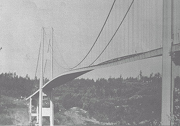
Introduction
The original Tacoma Narrows Bridge was
opened to traffic on July 1, 1940. It was located in Washington
State, near Puget Sound.
The Tacoma Narrows Bridge was the third-longest
suspension bridge in the United States at the time, with a length
of 5939 feet including approaches. Its two supporting towers
were 425 feet high. The towers were 2800 feet apart.
Design
Prior to this time, most bridge designs
were based on trusses, arches, and cantilevers to support heavy
freight trains. Automobiles were obviously much lighter. Suspension
bridges were both more elegant and economical than railway bridges.
Thus the suspension design became favored for automobile traffic.
Unfortunately, engineers did not fully understand the forces
acting upon bridges. Neither did they understand the response
of the suspension bridge design to these poorly understood forces.
Furthermore, the Tacoma Narrows Bridge
was built with shallow plate girders instead of the deep stiffening
trusses of railway bridges. Note that the wind can pass through
trusses. Plate girders, on the other hand, present an obstacle
to the wind.
As a result of its design, the Tacoma
Narrows Bridge experienced rolling undulations which were driven
by the wind. It thus acquired the nickname "Galloping Gertie."
Failure
Strong winds caused the bridge to collapse
on November 7, 1940. Initially, 35 mile per hour winds excited
the bridge's transverse vibration mode, with an amplitude of
1.5 feet. This motion lasted 3 hours.
The wind then increased to 42 miles per
hour. In addition, a support cable at mid-span snapped, resulting
in an unbalanced loading condition. The bridge response thus
changed to a 0.2 Hz torsional vibration mode, with an amplitude
up to 28 feet. The torsional mode is shown in Figures 1a and
1b.

Figure 1a. Torsional Mode of the Tacoma
Narrows Bridge

Figure 1b. Torsional Mode of the Tacoma
Narrows Bridge
The torsional mode shape was such that the bridge was effectively
divided into two halves. The two halves vibrated out-of-phase
with one another. In other words, one half rotated clockwise,
while the other rotated counter-clockwise. The two half spans
then alternate polarities.
One explanation of this is the "law of minimum energy."
A suspension bridge may either twist as a whole or divide into
half spans with opposite rotations. Nature prefers the two half-span
option since this requires less wind energy.
The dividing line between the two half
spans is called the "nodal line." Ideally, no rotation
occurs along this line.
The bridge collapsed during the excitation
of this torsional mode. Specifically, a 600 foot length of the
center span broke loose from the suspenders and fell a distance
of 190 feet into the cold waters below. The failure is shown
in Figures 2a and 2b.

Figure 2a. Failure of the Tacoma Narrows
Bridge

Figure 2b. Tacoma Narrows Bridge after
the Failure
Failure Theories
Candidates
The fundamental weakness of the Tacoma
Narrows Bridge was its extreme flexibility, both vertically and
in torsion. This weakness was due to the shallowness of the stiffening
girders and the narrowness of the roadway, relative to its span
length.
Engineers still debate the exact cause
of its collapse, however. Three theories are:
1. Random turbulence
2. Periodic vortex shedding
3. Aerodynamic instability (negative damping)
These theories are taken from Reference
1. Aerodynamic instability is the leading candidate.
Random Turbulence
An early theory was that the wind pressure
simply excited the natural frequencies of the bridge. This condition
is called "resonance." The problem with this theory
is that resonance is a very precise phenomenon, requiring the
driving force frequency to be at, or near, one of the system's
natural frequencies in order to produce large oscillations. The
turbulent wind pressure, however, would have varied randomly
with time. Thus, turbulence would seem unlikely to have driven
the observed steady oscillation of the bridge.
Vortex Shedding
Theodore von Karman, a famous aeronautical
engineer, was convinced that vortex shedding drove the bridge
oscillations. A diagram of vortex shedding around a spherical
body is shown in Figure 3. Von Karman showed that blunt bodies
such as bridge decks could also shed periodic vortices in their
wakes.
A problem with this theory is that the
natural vortex shedding frequency was calculated to be 1 Hz.
This frequency is also called the "Strouhal frequency."
The torsional mode frequency, however, was 0.2 Hz. This frequency
was observed by Professor F. B. Farquharson, who witnessed the
collapse of the bridge. The calculated vortex shedding frequency
was five times higher than the torsional frequency. It was thus
too high to have excited the torsional mode frequency.
In addition to "von Karman"
vortex shedding, a flutter-like pattern of vortices may have
formed at a frequency coincident with the torsional oscillation
mode. Whether these flutter vortices were a cause or an effect
of the twisting motion is unclear.

Figure 3. Vortex Shedding around a Spherical
Body
Aerodynamic Instability
Aerodynamic instability is a self-excited
vibration. In this case, the alternating force that sustains
the motion is created or controlled by the motion itself. The
alternating force disappears when the motion disappears. This
phenomenon is also modeled as free vibration with negative damping.
Airfoil flutter and transmission line
galloping are related examples of this instability. Further explanations
of instability are given in References 2 , 3, and 4.
The following scenario shows how aerodynamic
instability may have caused the Tacoma Narrows Bridge to fail.
For simplicity, consider the motion of only one span half.
Assume that the wind direction was not
perfectly horizontal, perhaps striking the bridge span from below,
as shown in Figure 4a

Thus, the bridge is initially at an angle-of-attack
with respect to the wind. Aerodynamic lift is generated because
the pressure below the span is greater than the pressure above.
This lift force effectively places a torque, or moment, on the
bridge. The span then begins to twist clockwise as show in Figure
4b. Specifically, the windward edge rotates upward while the
leeward edge rotates downward.

The span has rotational stiffness, however. Thus, elastic strain
energy builds up as the span rotates. Eventually, the stiffness
moment overcomes the moment from the lift force. The span then
reverses its course, now rotating counter-clockwise
The span's angular momentum will not allow
it to simply return to its initial rest position, however. The
reason is that there is little or no energy dissipation mechanism.
Thus, the span overshoots its initial rest position. In fact,
it overshoots to the extent that the wind now strikes the span
from above as shown in Figure 4c. The wind's lift force now effectively
places a counter-clockwise moment on the span.

Once again, strain energy builds up in
the span material. Eventually, the stiffness moment exceeds the
moment from the wind's lift force. The span thus reverse course,
now rotating clockwise. Again, it overshoots its rest position.
The cycle of oscillation begins anew from the position shown
in Figure 4a, except that the span now has rotational velocity
as it passes through the original rest position.
The cycles of oscillation continue in
a repetitive manner.
Note that the wind force varies as a function
of the span angle during the cycle. The wind force may also vary
with the angular velocity. The wind force is not a function of
time, however.
Eventually, one of two failure modes occurs.
One possibility is that the span experiences fatigue failure
due to an excessive number of stress reversals. The other is
that the angular displacement increased in an unstable manner
until the material is stressed beyond its yield point, and then
beyond its ultimate stress limit.
In reality, these two failure modes are
interrelated. For example, accumulated fatigue effectively lowers
the yield and ultimate stress limits. Regardless, the bridge
collapses.
As a final note, the aerodynamic instability
oscillation is not a resonant oscillation since the wind does
not have a forcing frequency at, or near, the bridge's torsional
mode frequency. Some physics and engineering textbooks mistakenly
cite the Tacoma Narrows Bridge as an example of resonance. This
problem is discussed in Reference 5.
Nevertheless, the bridge's collapse remains
the most well-know structural failure due to vibration.
Replacement Bridge
A new Tacoma Narrows Bridge was built
in 1950, as shown in Figure 5. The second bridge had truss-girders
which allowed the winds to pass through. It also had increased
torsional stiffness because it was thicker and wider. Furthermore,
wind tunnel testing was performed to verify the design of the
new bridge prior to its construction.
References

Figure 5. The Replacement Tacoma Narrows
Bridge, Built in 1950
|