Wind Chime Acoustics
 |
History
A number of cultures throughout history have enjoyed the pleasing sounds of wind bells and wind chimes. Widespread use of wind chimes can be traced to ancient China.
The Chinese became excellent metal workers, particularly in refining iron, around the year 1000 B.C. They began producing wind bells at this time for ritual ceremonies.
The use of wind chimes spread to Japan around 400 B.C. The Japanese used these chimes in Buddhist temples as well as in home gardens.
The Japanese produced a bronze wind bell called dotaku. They later developed a smaller and lighter wind chime called the furin, made from glass, metal or ceramics. The furin chimes were often hand painted.
|
|
The wind chimes enjoyed by western cultures today are typically made from rods of varying lengths suspended from a rack. This design became popular in the 19th century. This design is partly due to a musician who sought to improve the tone of the bells he played in an orchestra. Entrepreneurial Victorians, remembering the Japanese furin, popularized this design.
Author’s Wind Chime
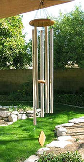
The wind chime model is “Cavernous Echoes” by Majesty Bells, as shown in the image at the top of the page. The vendor’s brochure states that this is a five note wind chime hand-tuned to the scale of E. The material is anodized aluminum. The outer diameter is 1.25 inch. The chimes are hollow, with a wall thickness of 3/32 inch. The boundary condition is essentially free-free for vibration calculations. The condition is open-open for acoustic frequency.
The chimes have three wooden parts, which are from top to bottom: the head, the striker, and the wind catcher.
|
Experiment
Assume that the wind chimes have three types of possible responses as shown in Table 1. Furthermore, each type has higher modes. One of the objectives is to determine which mode type or types produce the chimes pleasing sound. The natural frequencies are calculated using textbook formulas.
In addition, the chimes also have a ring frequency corresponding to a breathing mode. This frequency is 50,540 Hz for each chime, since the chimes have a common diameter. This frequency is well above the upper frequency limit of human hearing, however.
The wind chimes were excited separately using the striker. The resulting responses were due to the bending modes in each case. Note that the bending mode is the only type in Table 1 that has non-integer harmonics, however. In this sense, wind chimes are atonal.
|
Frequency Response Data
The response data is summarized in Table 2. The musical note is the nearest note to the measured frequency.
The sequence: E, F#, G#, A, B, represents the first five tones of the E major scale. The complete E major scale contains this sequence plus C# and D#.
The second natural frequency of each chime represents a note in the E scale, as shown in Table 2.
|
Table 1. Wind Chime Fundamental Frequencies
|
Chime
|
Length
(inch)
|
Vibration
Bending
(Hz)
|
Vibration
Longitudinal
(Hz)
|
Acoustical
Longitudinal
(Hz)
|
|
1
|
34.69
|
238
|
2832
|
194
|
|
2
|
32.56
|
271
|
3017
|
207
|
|
3
|
30.69
|
305
|
3201
|
219
|
|
4
|
29.94
|
320
|
3281
|
225
|
|
5
|
28.19
|
361
|
3485
|
238
|
|
Table 2. Measured Frequencies and Nearest Musical Notes
|
Chime 1
|
|
Chime 2
|
|
Chime 3
|
|
Chime 4
|
|
Chime 5
|
|
|
Freq (Hz)
|
Note
|
Freq (Hz)
|
Note
|
Freq (Hz)
|
Note
|
Freq (Hz)
|
Note
|
Freq (Hz)
|
Note
|
|
244
|
B
|
278
|
C
|
312
|
D
|
330
|
E
|
371
|
F#
|
|
663
|
E
|
753
|
F#
|
850
|
G#
|
890
|
A
|
1000
|
B
|
|
1272
|
D#
|
1441
|
F#
|
1625
|
G#
|
1700
|
G#
|
3031
|
F#
|
|
2050
|
C
|
2314
|
D
|
2600
|
E
|
2712
|
D#
|
4351
|
C#
|
|
Sound Files
|
Waterfall Plots
Waterfall plots for each of the five chimes are given in Figures 1 through 5, respectively. The vertical axis is the Fourier transform magnitude, which has an arbitrary scale factor. Each axis scale is linear.
The corresponding frequencies for each chime are given in the accompanying tables. The calculated frequency is the bending frequency. The measured frequencies have reasonably good agreement for the calculated frequency for each chime.
The waterfall plots show the relative difference in amplitude between the various natural frequencies within each chime.
The extent to which each mode is excited depends in part on the impact location of the striker against the chime.
Whether the manufacturer considered the complexity of nodal lines when designing the striker position is unclear. The waterfall plots also show the how the reverberation time varies between the natural frequencies. The fundamental frequency is the frequency with the longest reverberation time for each chime.
The peak amplitude response, however, may occur at the second or third natural frequency for a given chime.
|
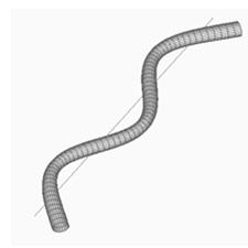
Bending Mode Shapes
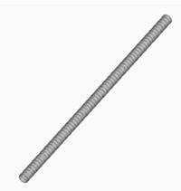
A geometry model of chime 1 is shown in Figure 6.
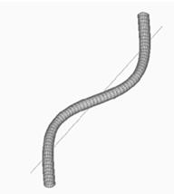
The first through third bending mode shapes are shown in Figures 7 through 9, respectively. The mode shapes are greatly exaggerated, with an arbitrary scale factor.
|
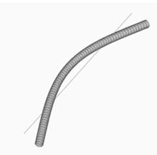 |
Figure 6. Chime 1, Undeformed Model
|
Figure 7. Chime 1, First Bending Mode
|
|
|
Figure 8. Chime 1, Second Bending Mode
|
Figure 9. Chime 1, Third Bending Mode
|
|